Benjamin Sheng

F1 Sim Rig

Skills: Fusion 360, Woodworking

June 2022 - September 2023

Being a huge fan of the F1 games, I wanted to create the most accurate simulation of being an F1 driver. I had a few requirements for this project:

1. It must look like a real monocoque

2. It must be low-cost

3. It must be relatively light (so I can move it around)

intro image

Sim Rig Frame

Any sim rig needs a frame to withstand the forces it will be put under. The turning of the wheel and slamming of the brakes put a lot of stress on a rig, which is why it is paramount to have a frame. The frame will help maintain the rig's shape and give it the necessary strength. It also allows for simple mounting points to attach elements to hold the chair (the white 3D prints) or the panels on the outside.

To aid the rig's mobility, the frame can be split into two, each detailed below. They are connected by 6 screws, 3 on each side.

Sim Rig Frame Top View Sim Rig Frame Isometric View Sim Rig Frame Front View

Back Frame.

Back Frame isometric view Back Frame top-down view Back Frame front view Back Frame side view

The seat is mounted on the back frame. The white parts attached to certain frame elements are meant to attach a fabric bucket seat. They were to be 3D printed and mounted using bolts. They were never fully tested, but are 0.5 inches wide on either side of the wood for strength.

The three pieces of wood protruding from the bottom of the frame are meant to hold the weight of the front frame. To keep the rig as realistic as possible, I did not want a peg at the front of the rig to support the legs of the driver. The three protruding from the bottom brace the three slanted pieces of wood. This allowed the weight from the front of the frame to be transferred away and distributed evenly. This was successfully tested with a real-life prototype later on.

Front Frame.

Front Frame isometric view Front Frame top-down view Front Frame front view Front Frame side view

The front frame is much simpler than the back. It has to be as lightweight as possible, as it is in the air without a support peg at the front. The slanted wood pieces from the front to the back of this section are also an effort to distribute the weight from the front (where the pedals and your feet will be) to the middle of the rig.

As a sim racer, I enjoy a stiff brake pedal. This means a ton of force was to be put on the rig when under braking. The plate at the front is a mounting point for the pedals that would allow for a very sturdy platform. The worst feeling is having your pedals slide forward mid-braking zone.

Built Rig Prototype

Built Rig Prototype Left View Built Rig Prototype Right View

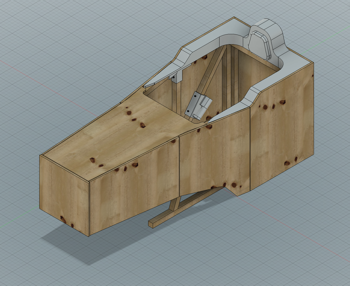
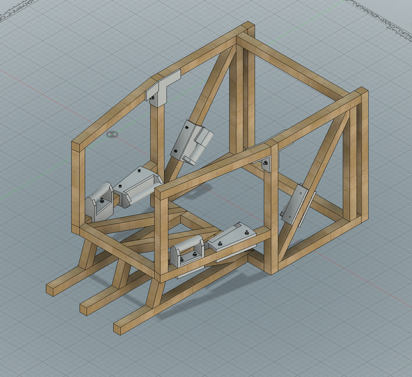
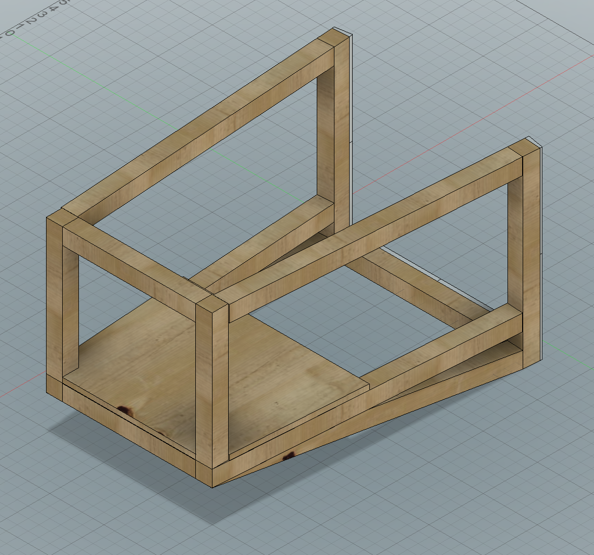
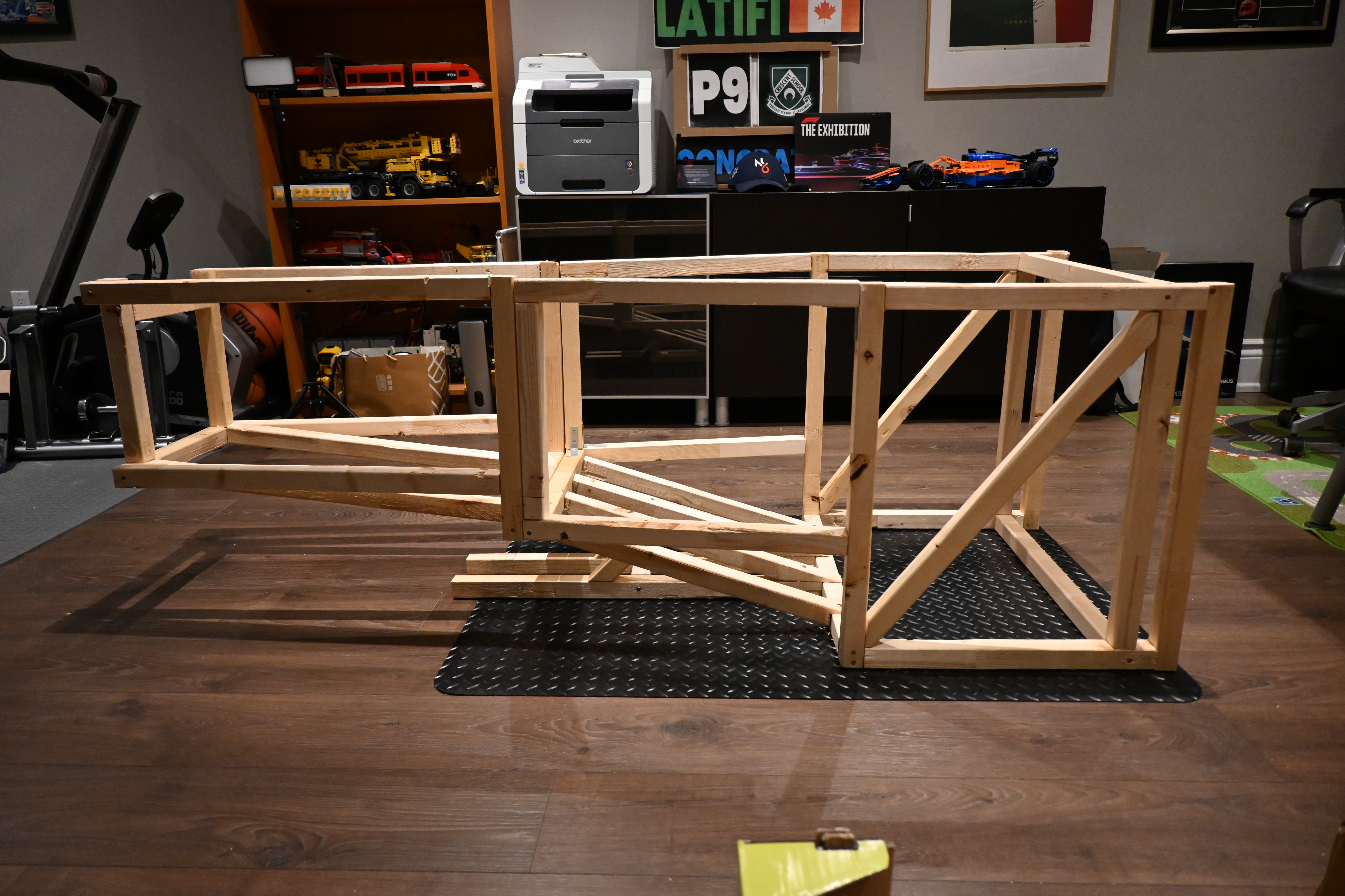
Unfortunately, I could only complete the rig's frame before I ran out of time and my parents' patience. Nevertheless, I learned a few lessons when building this prototype. (The photos above do not match the CAD 100% because I updated the rig on CAD, which I didn't get to in real life.)

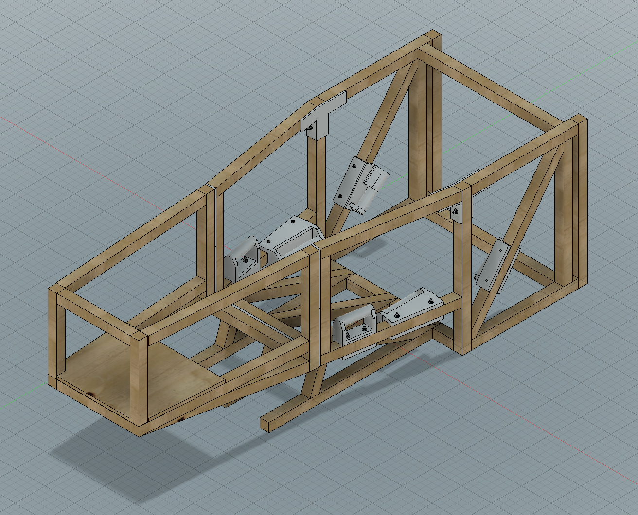
1. 2x2 Wood is not as Strong as you think.

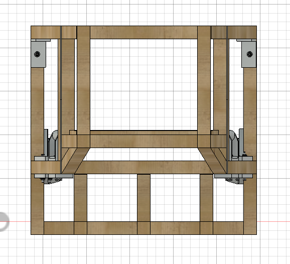
While the advantages of using 2x2 wood are its relative strength compared to its weight, the compromise is that there is a minimal surface area to connect pieces to. Only using one screw to attach pieces also allows it to rotate. This resulted in corners that were quite flimsy. While I fixed the issue by attaching 90-degree braces to hold the rig's shape, this issue was overlooked during the rig's design.

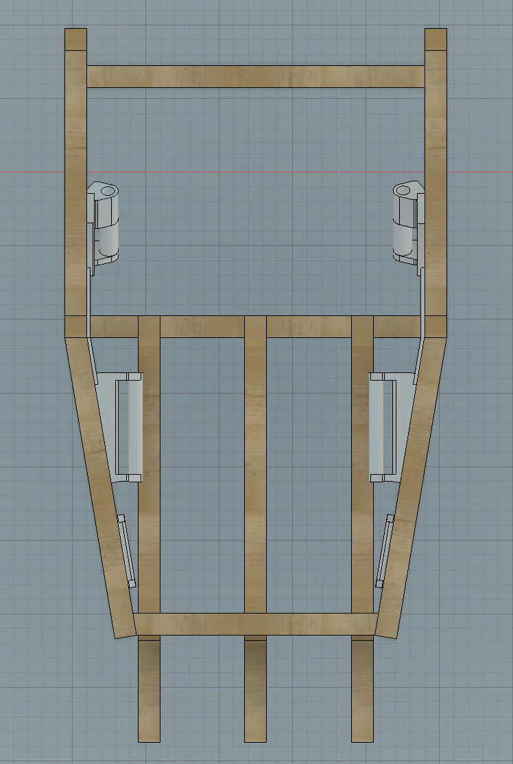
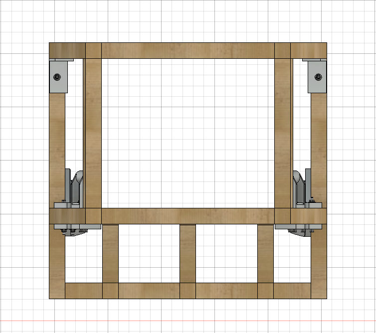
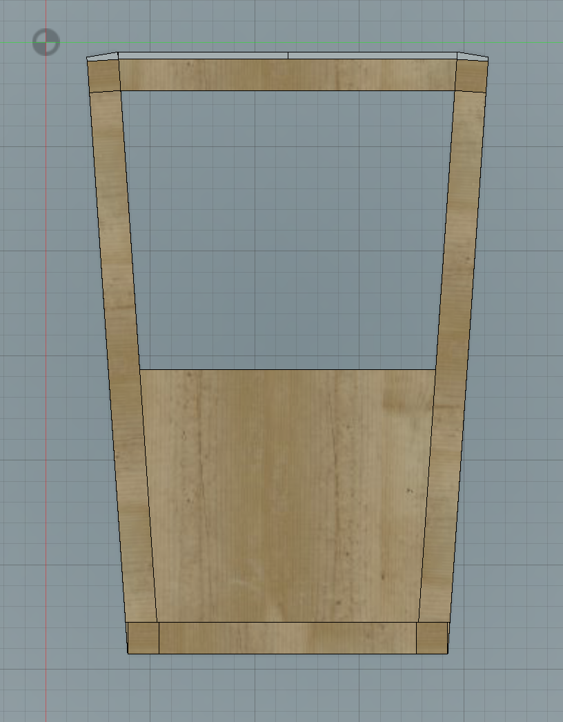
2. Fusion 360 to Life Miscorrelation

It is difficult to get a rig square - While it is easy to add angles and crazy parts in CAD, these are hard to replicate in real life. Even a 90-degree corner is tricky, as the wood may not be 100% square. Initially, the angle from the back to the front was a curve (don't ask me how I would do that), which would have been a nightmare. You can tell in the first photo that the rig looks slightly off even when finished.

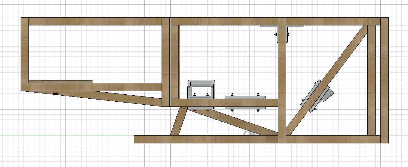
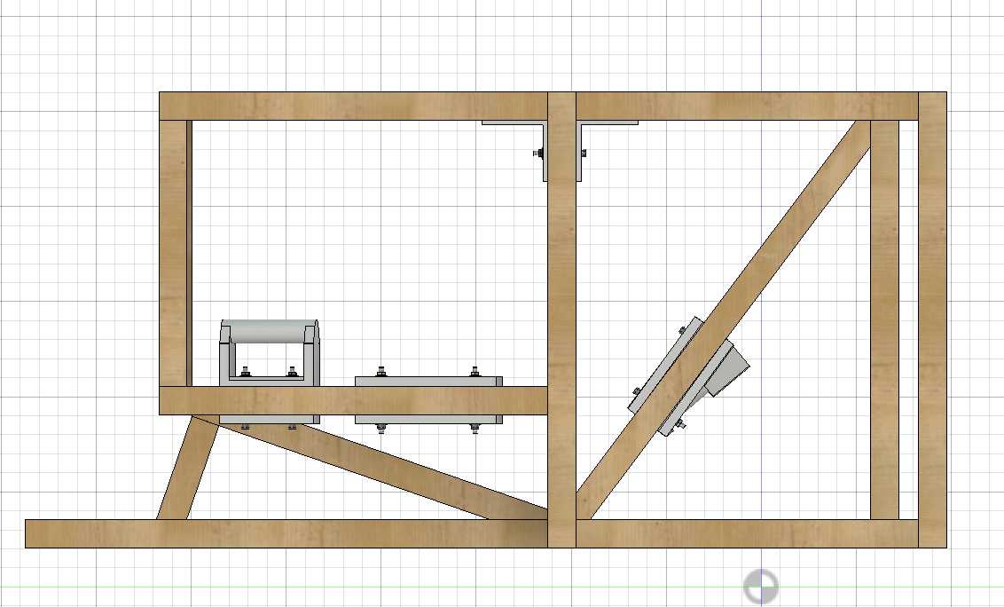
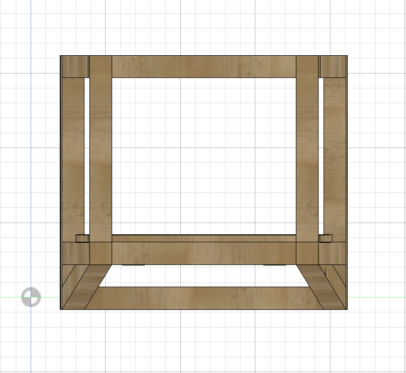
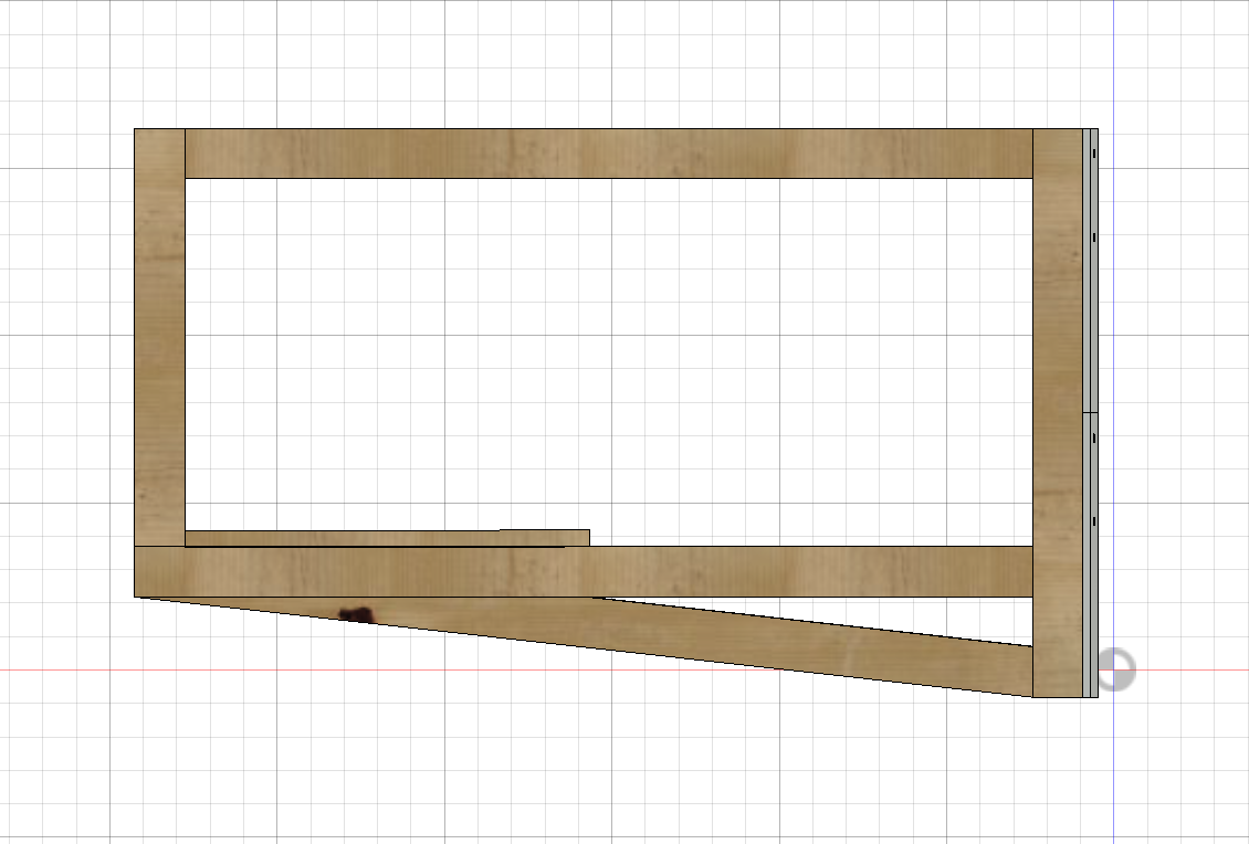
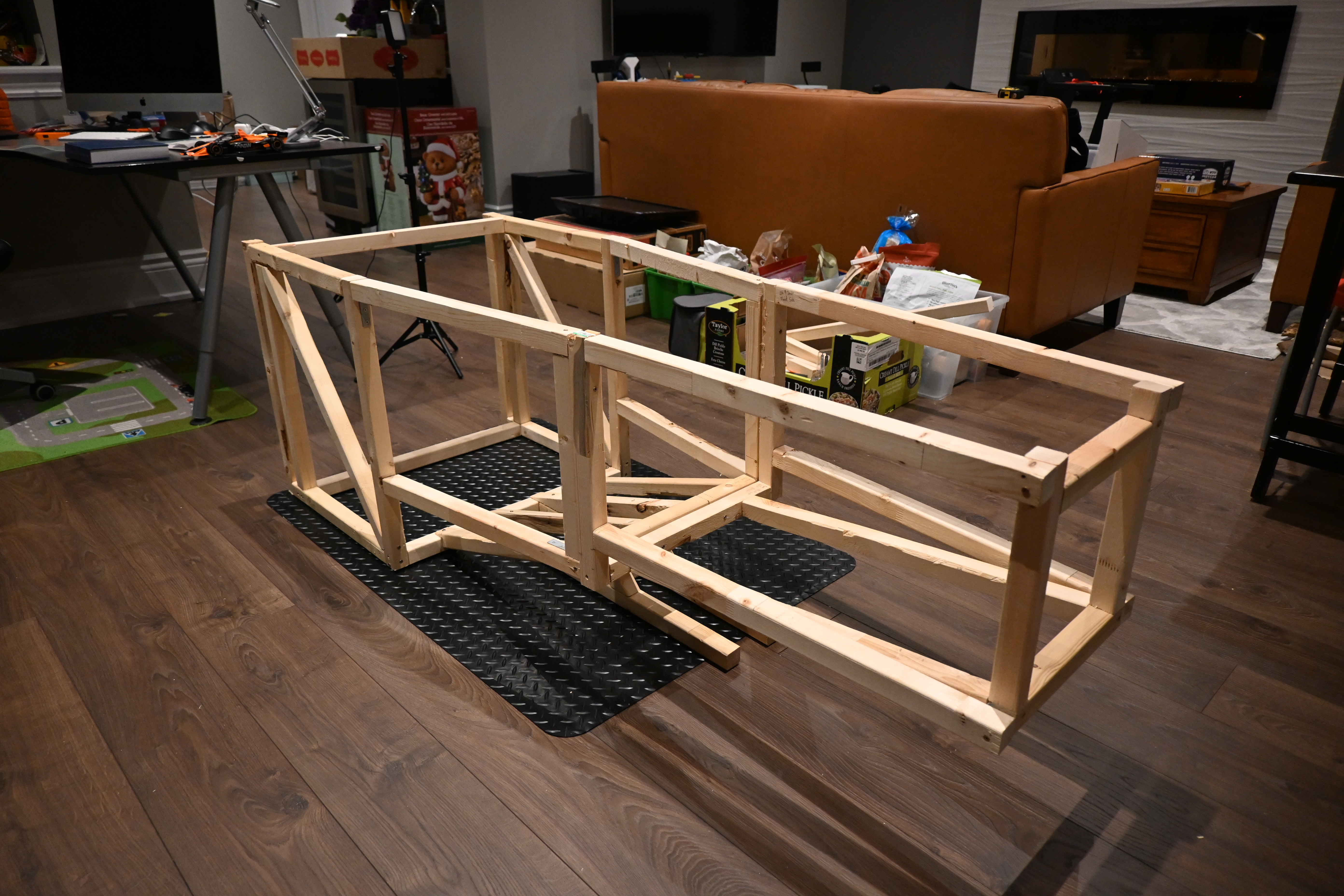
3. Dont Underestimate Your Weight

Initially, the three protruding parts from the bottom were two parts and closer together. This was a massive oversight as the weight was highly concentrated in the middle of the rig. This meant that those pieces broke when pressure was put on the sides. As shown in the CAD above, I modified this to three and spread more evenly apart, allowing from the weight to be distributed properly.