Benjamin Sheng

Windshield

Skills: Thermoforming, Test Jigs, Waterjetting, Solidworks

September 2025 - Present

My first project on UBC Solar was to re-design and re-optimize our windshield. This re-design must include methods to make the windshield more aerodynamic and more resilient to thermal expansion. Here are some key targets:

1. Windshield doesn't crack under thermal expansion

2. Screws are not pretruding (Reduce Drag)

3. Keep the cost low

intro image

Sponsor Communication

PDF

On any design team, we are always searching for new sponsors. One of the best ways to solve the issue of the windshield cracking under thermal expansion is to have it professionally thermoformed. This is very expensive so the first part of this project was me trying to get a plastics company to sponsor us or get us a discounted rate.

The document to the right is the file I sent to our prospective sponsor, along with our sponsorship package. In this document, I detail what the project entails, the issues with our previous windshield, the deadlines and the premilimary designs that I had made in Solidworks.

This experience allowed me to practice my communication skills with sponsors and understand what companies are looking for in order to secure a sponsorship. We are currently still in the process of securing a sponsor for this project but we are making progress.

As a back-up option, I tried to thermoform the windshield in house. This process is detailed below.

Thermoforming Test (Jig 1)

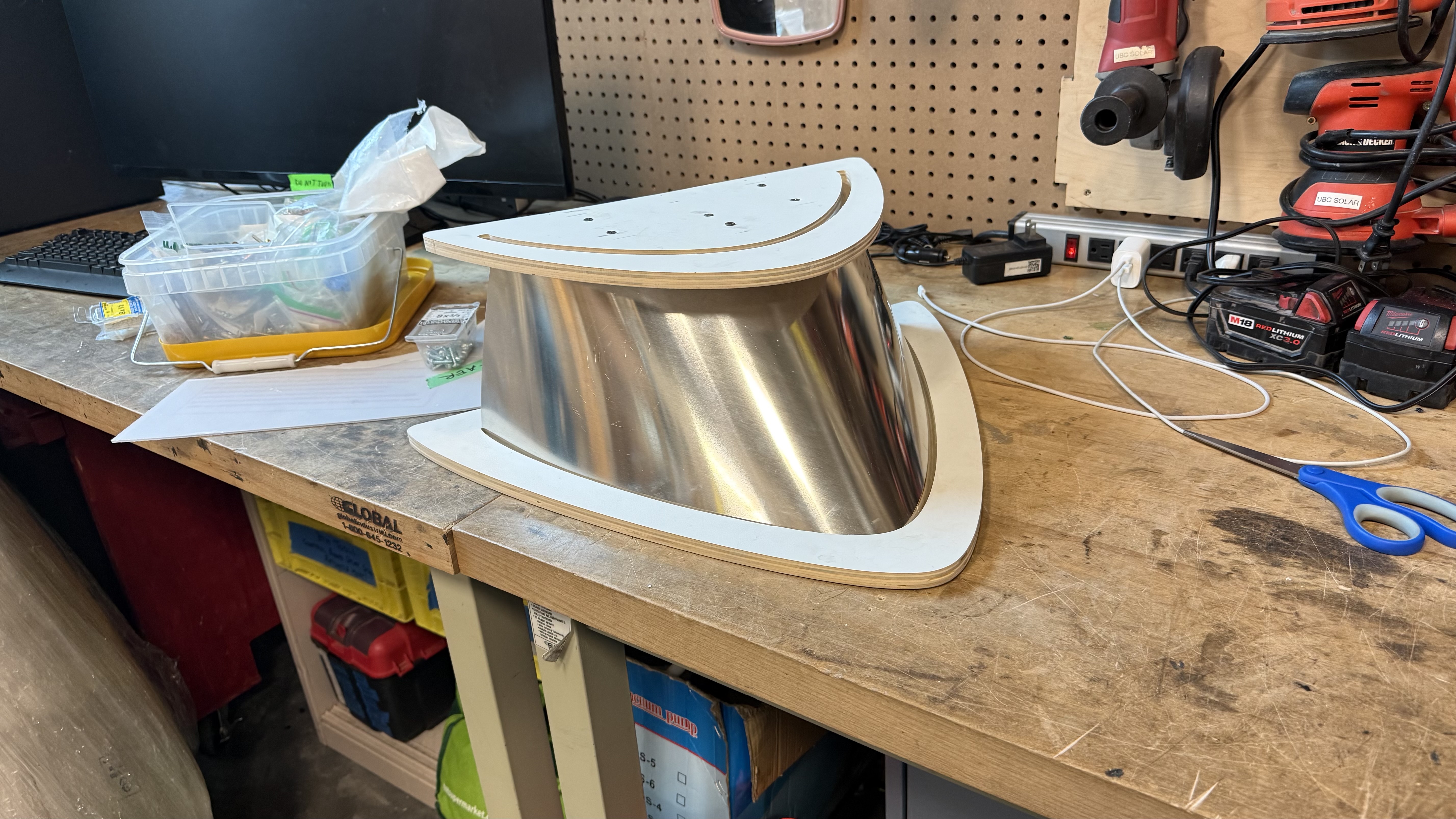
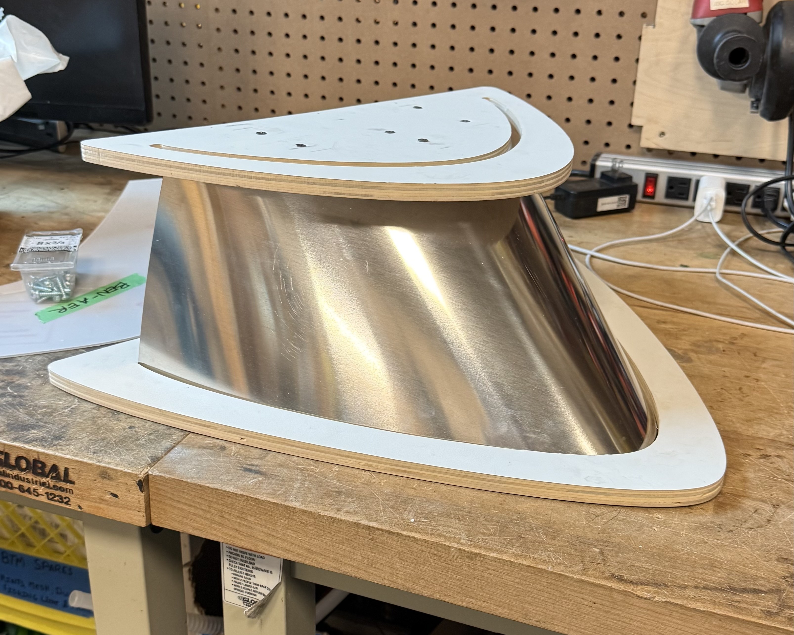
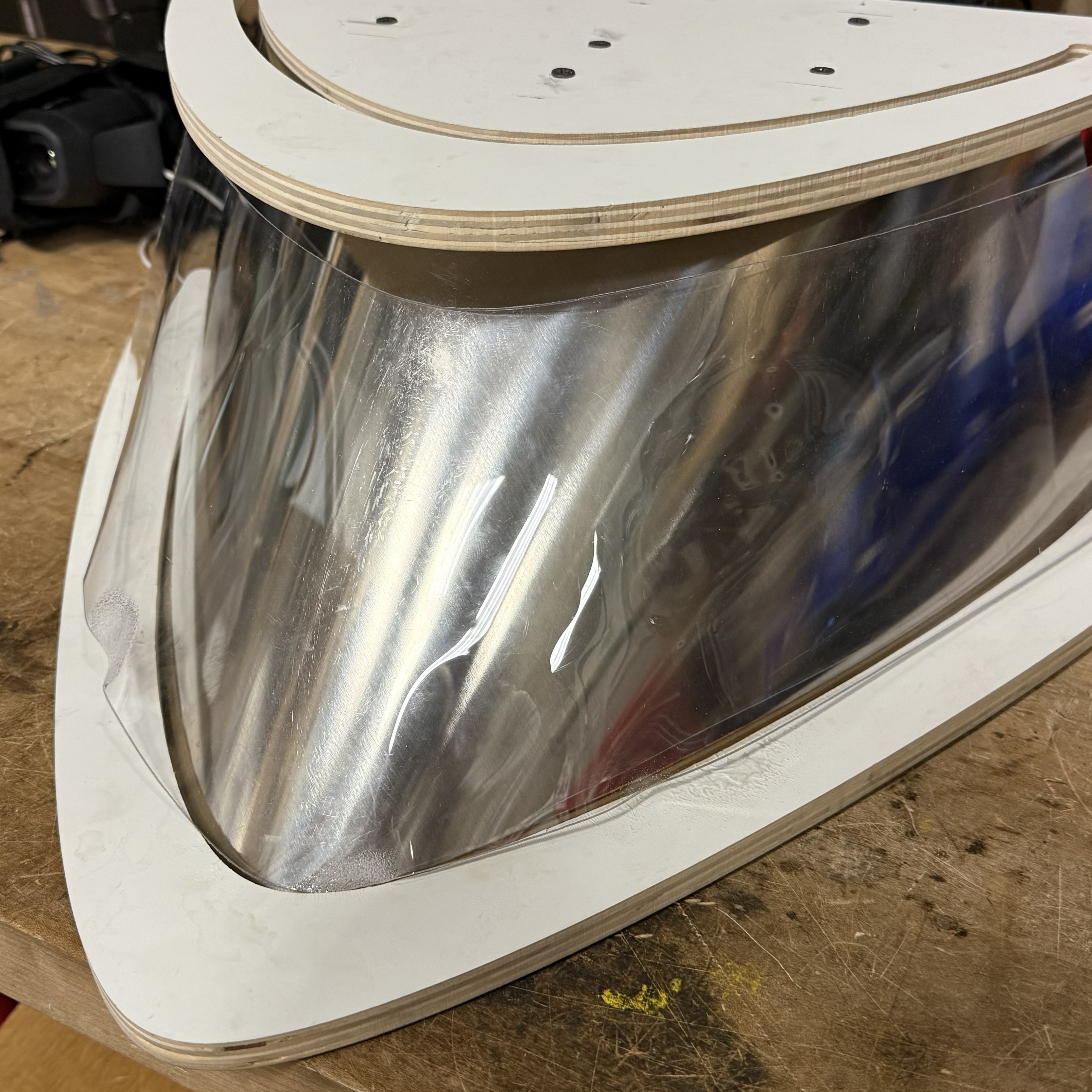
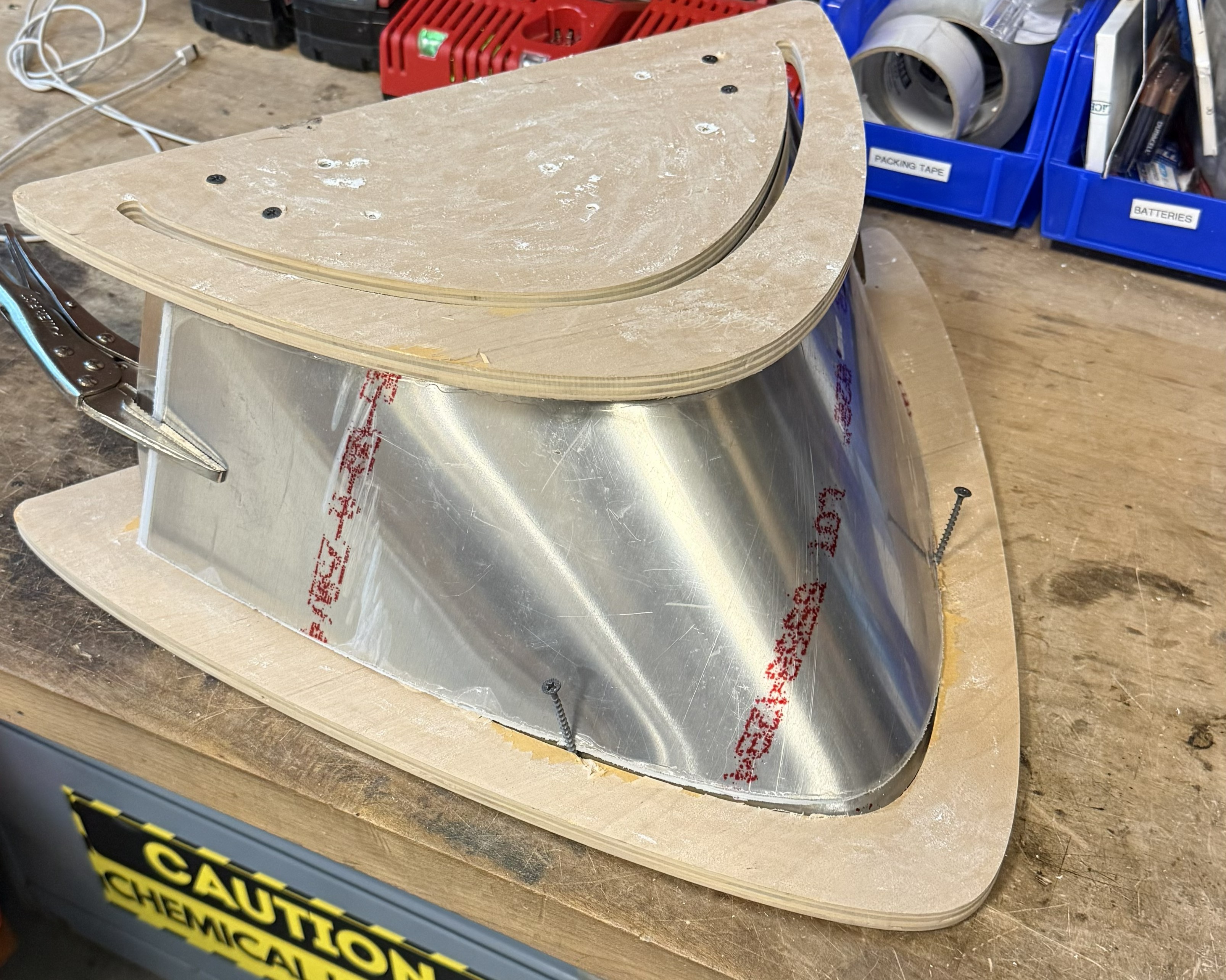
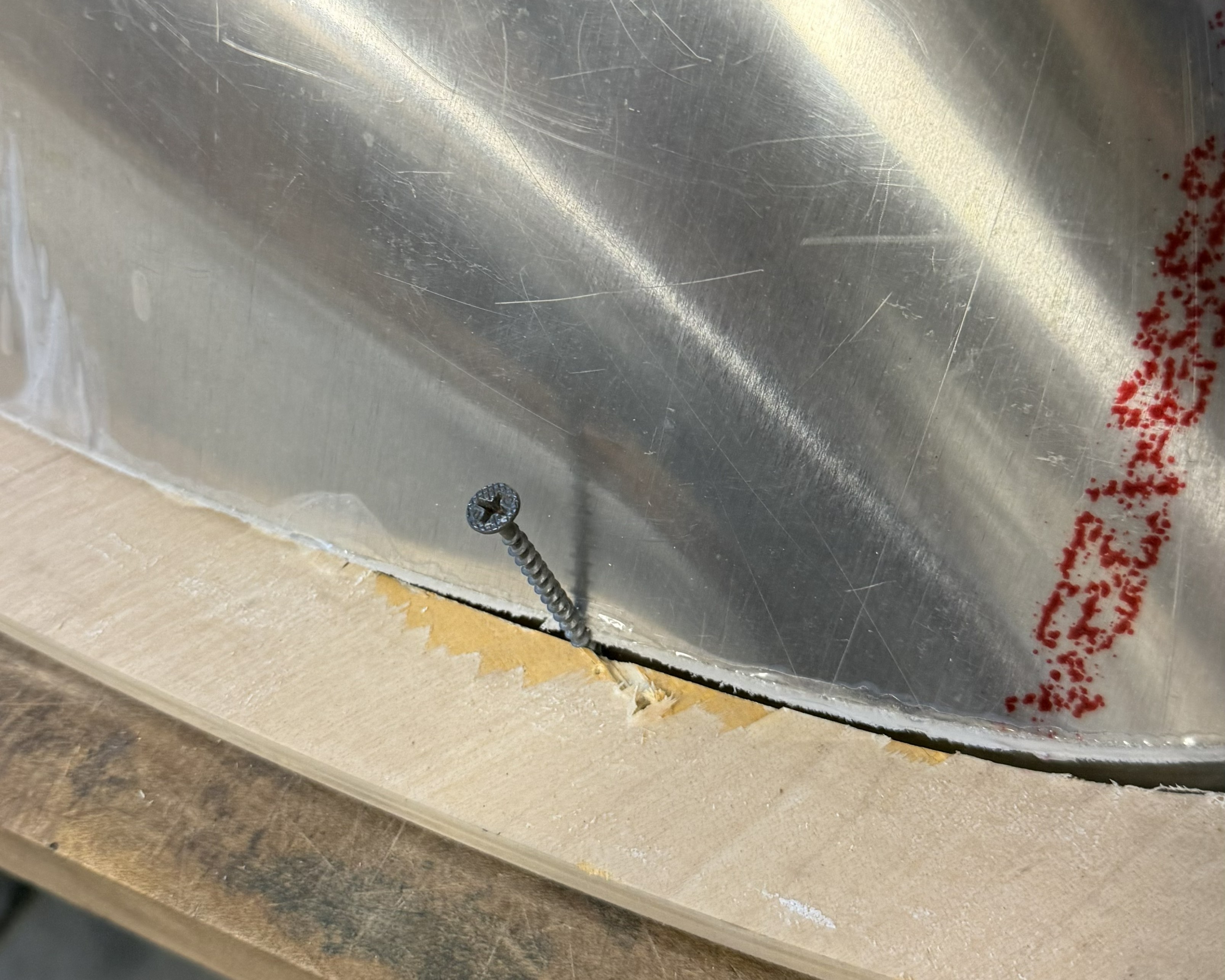
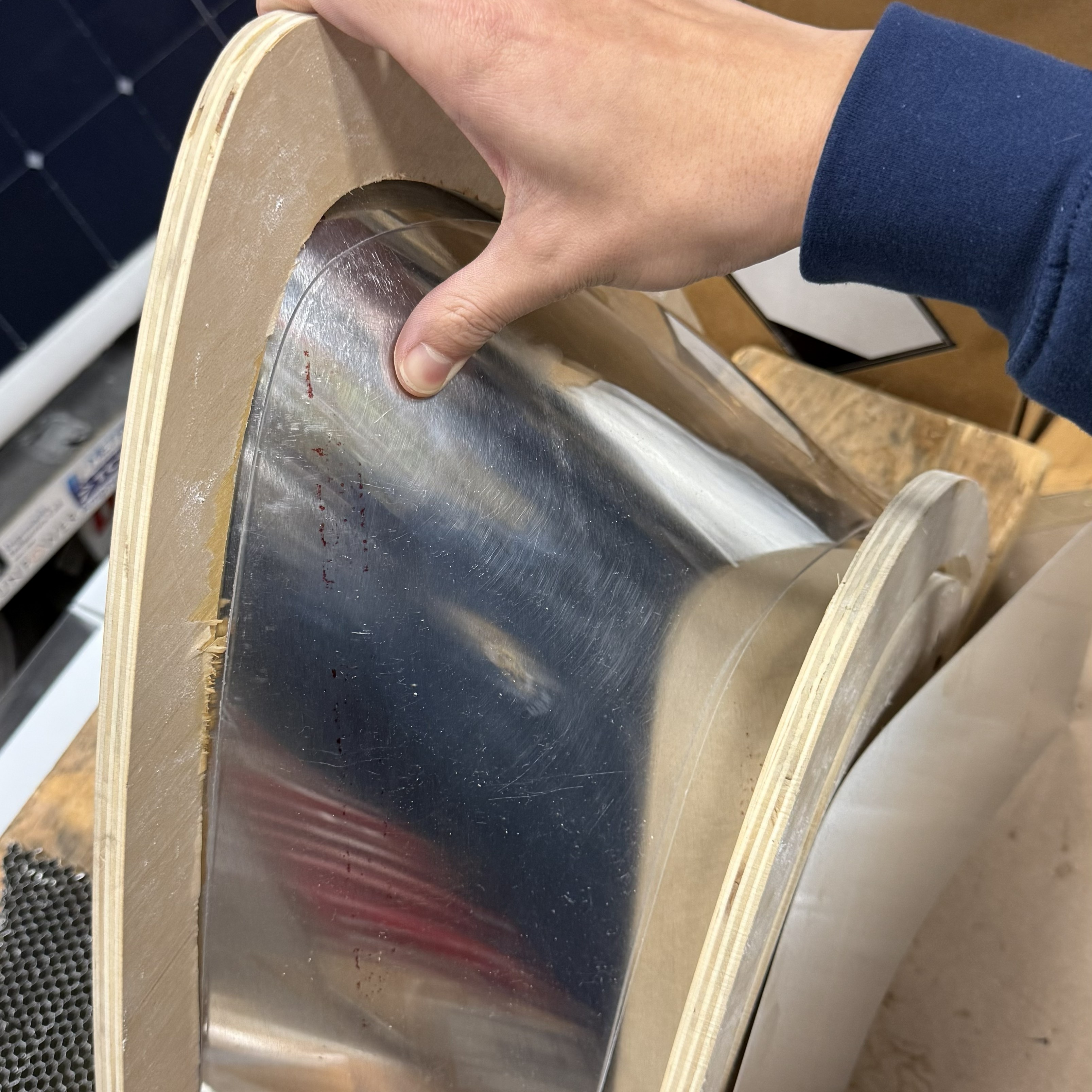
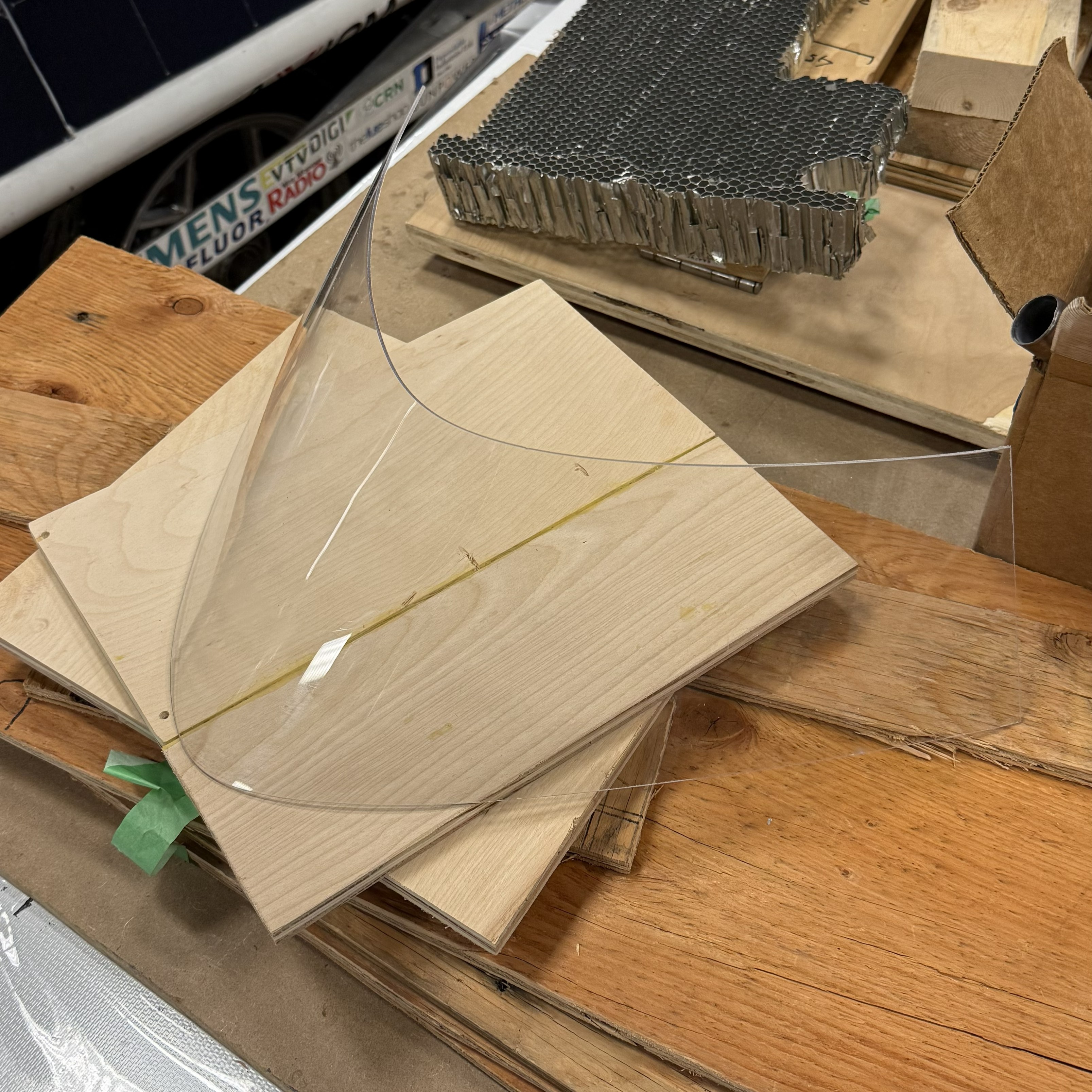
So, because thermoforming industrially seemed to be too expensive, I tried to do it in house. The photo on the right is a picture of my first test jig. It consists of two waterjetted pieces of wood, and a waterjet piece of aluminum and polycarbonate. I attached the two wooden pieces together with two by fours and wood screws. The aluminum is super flexible and was able to bend around a slot cut out in the wooden panels.

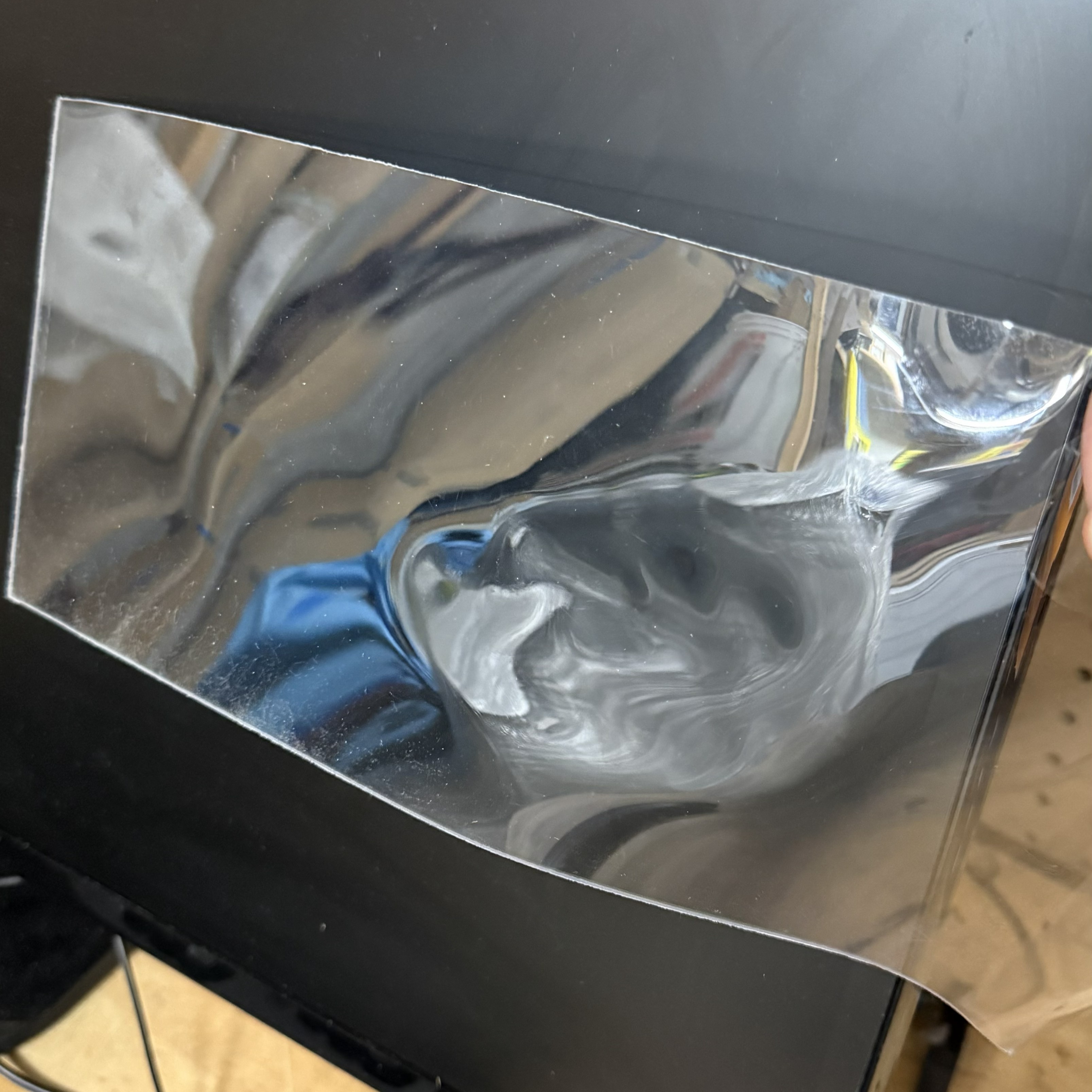
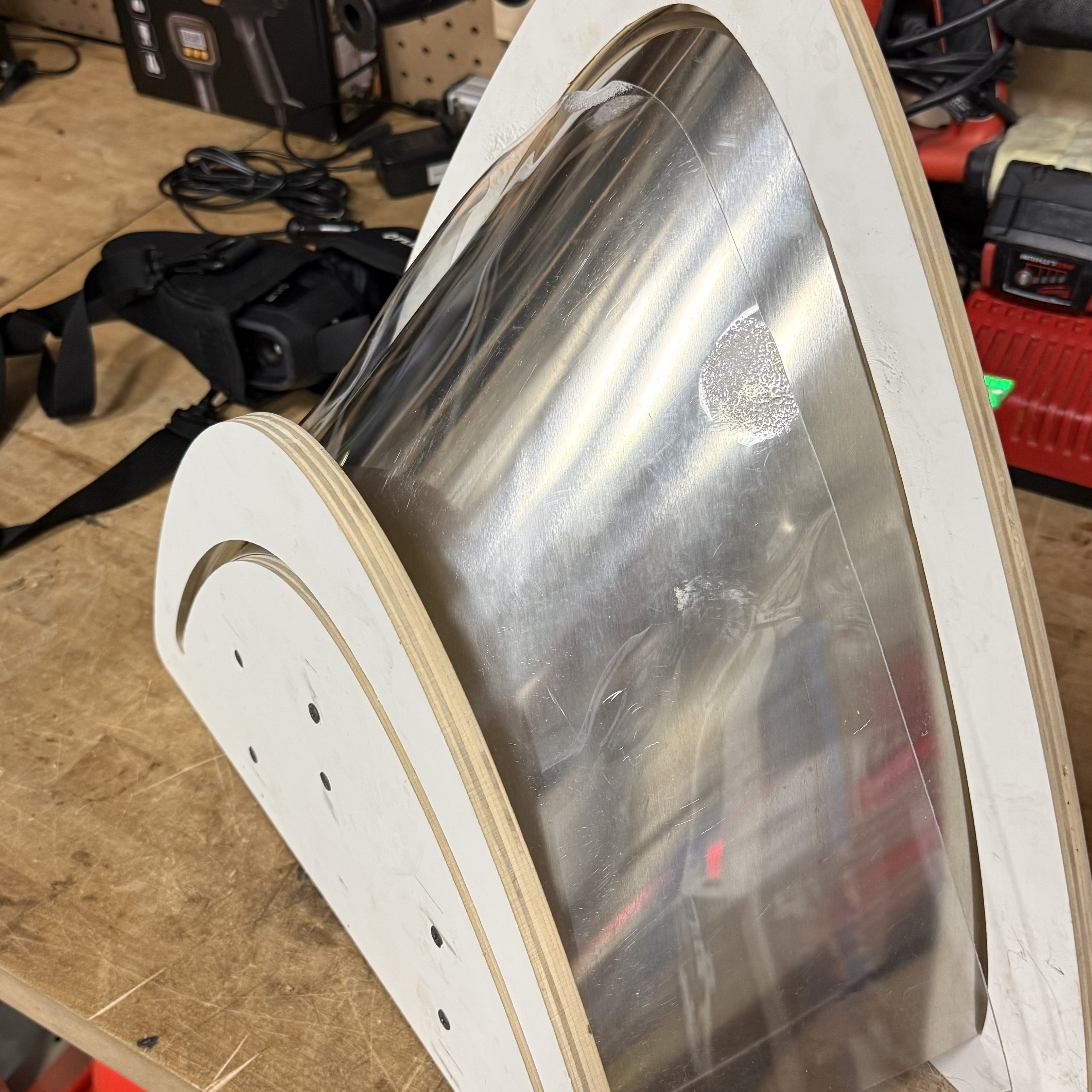
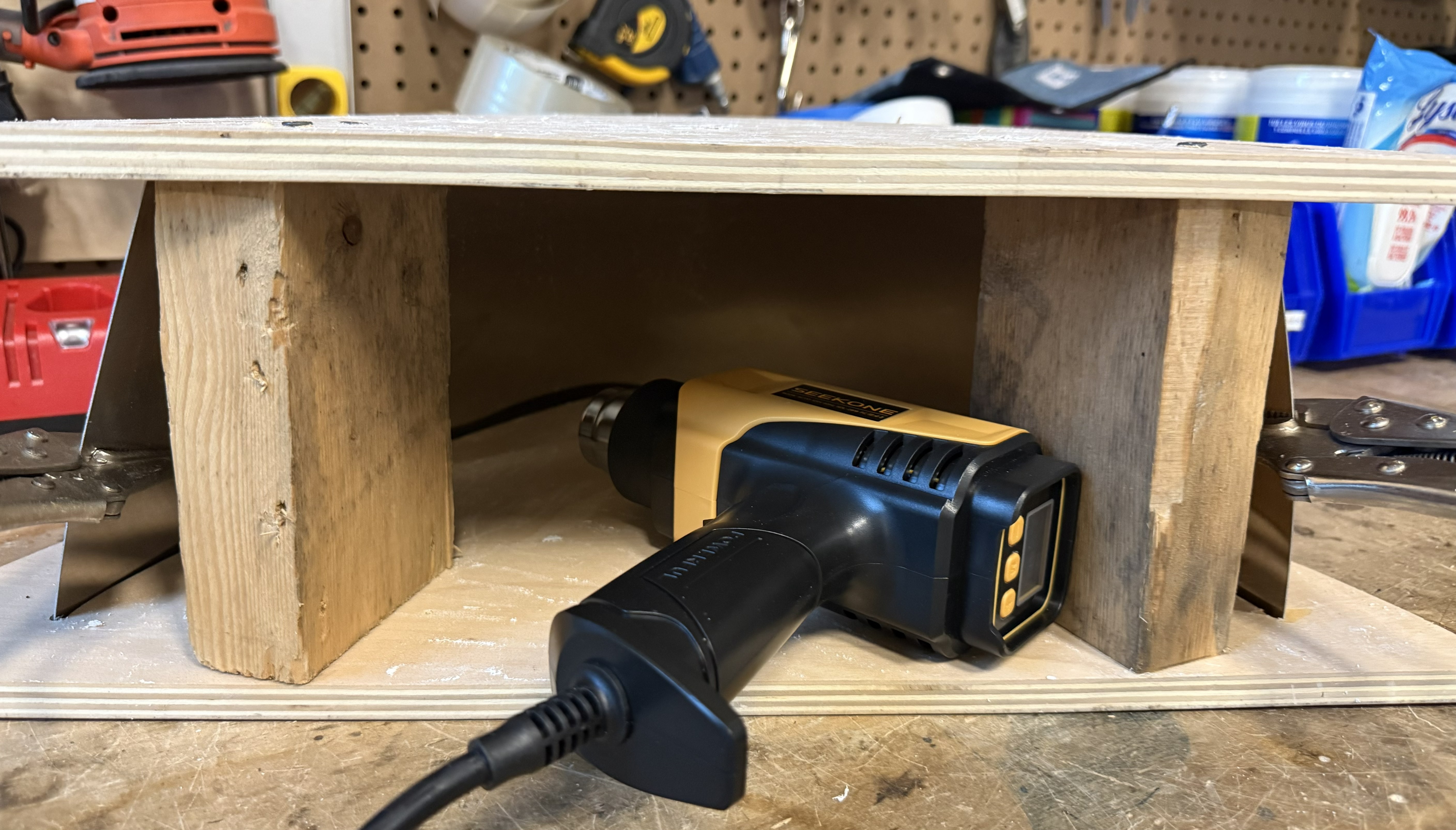
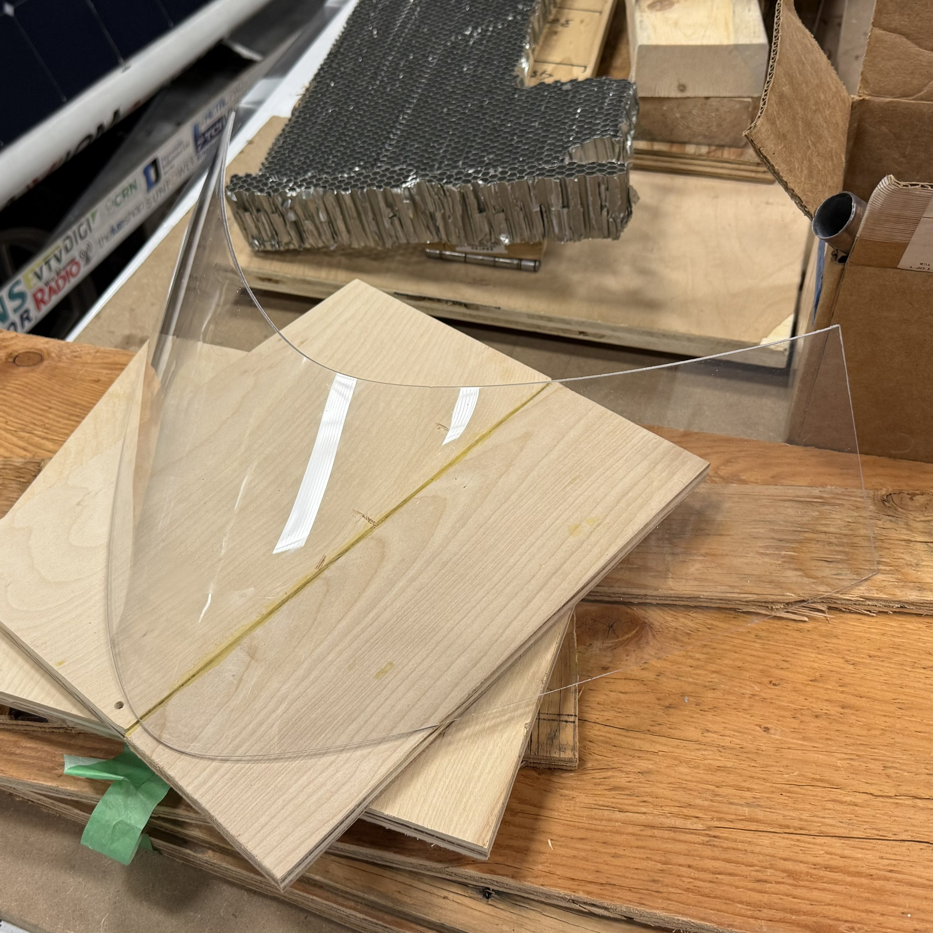
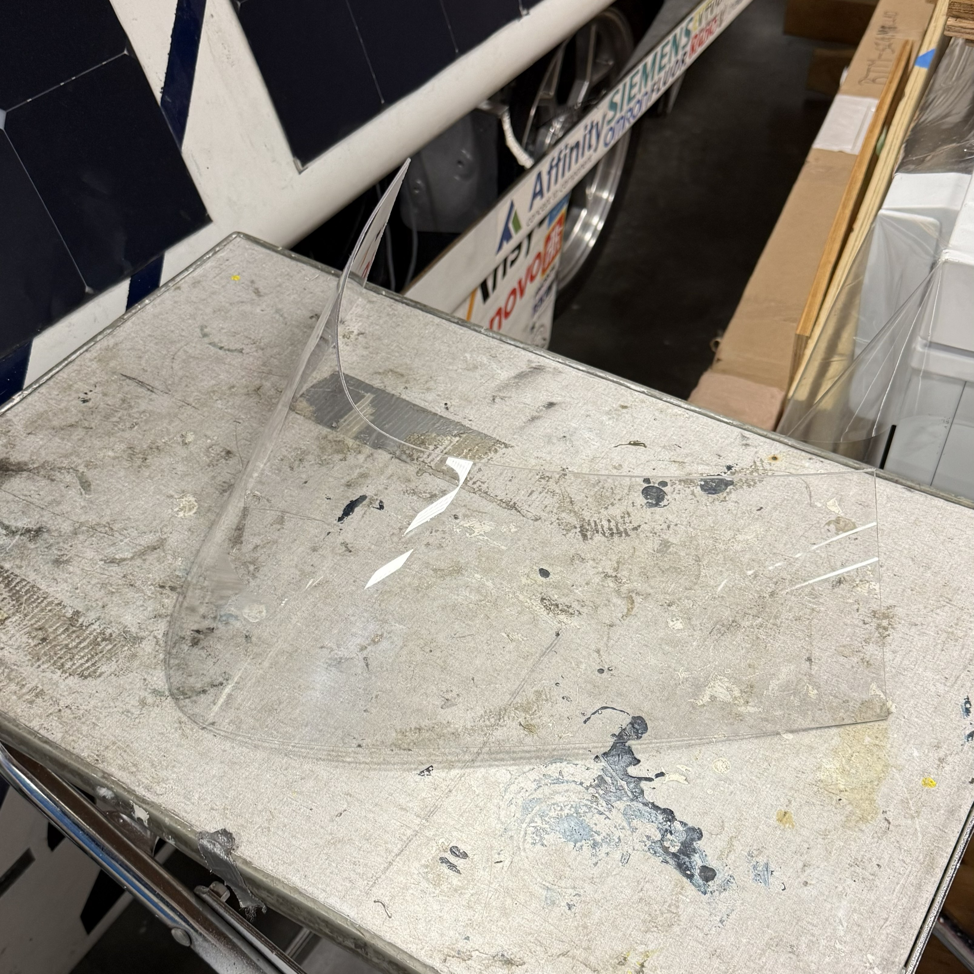
The way we were going to use this jig was to have the polycarbonate sheet stand vertically like in the photo to the right. Then we would go at it with a heat gun and let the polycarbonate fall onto the aluminum and form.

Built Rig Prototype

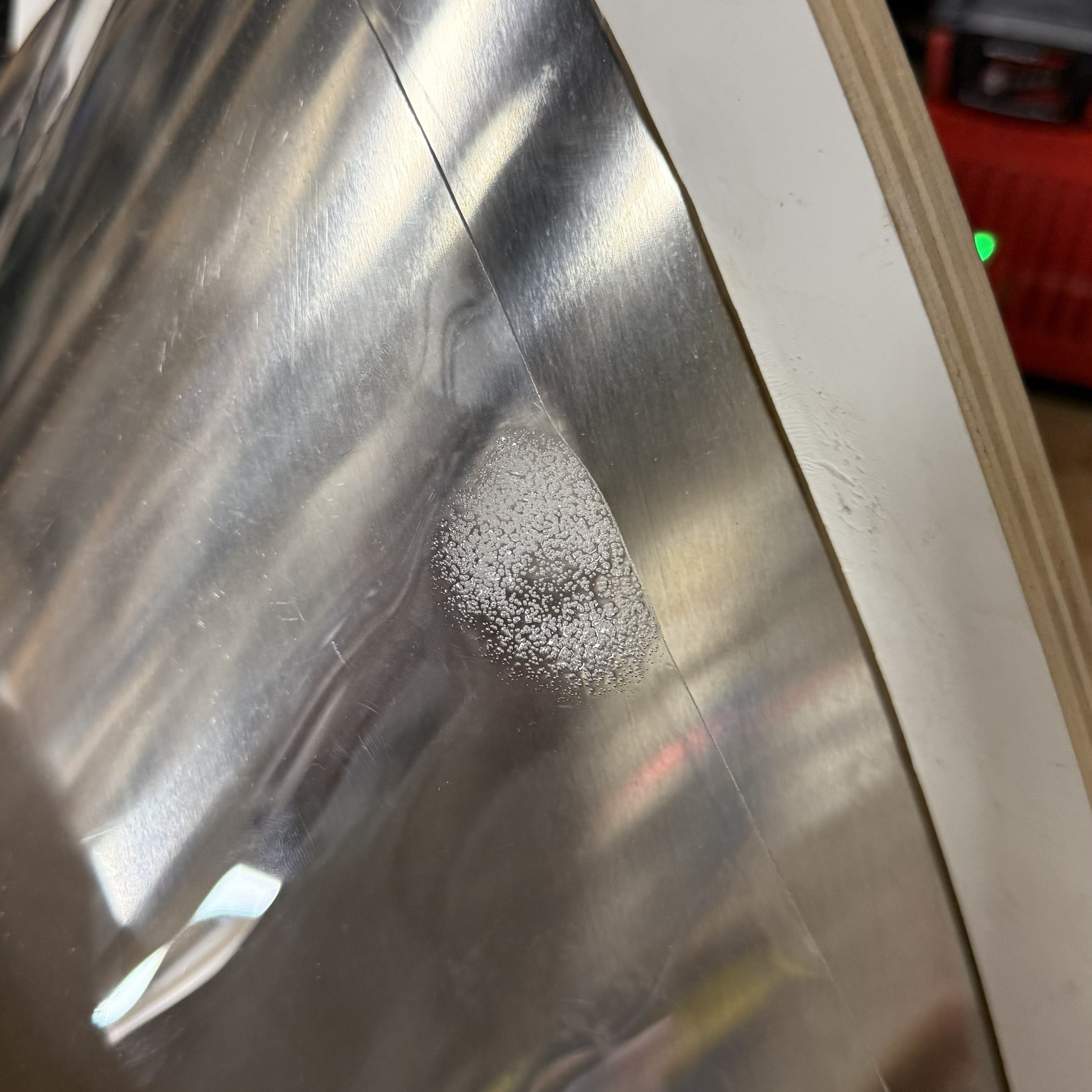
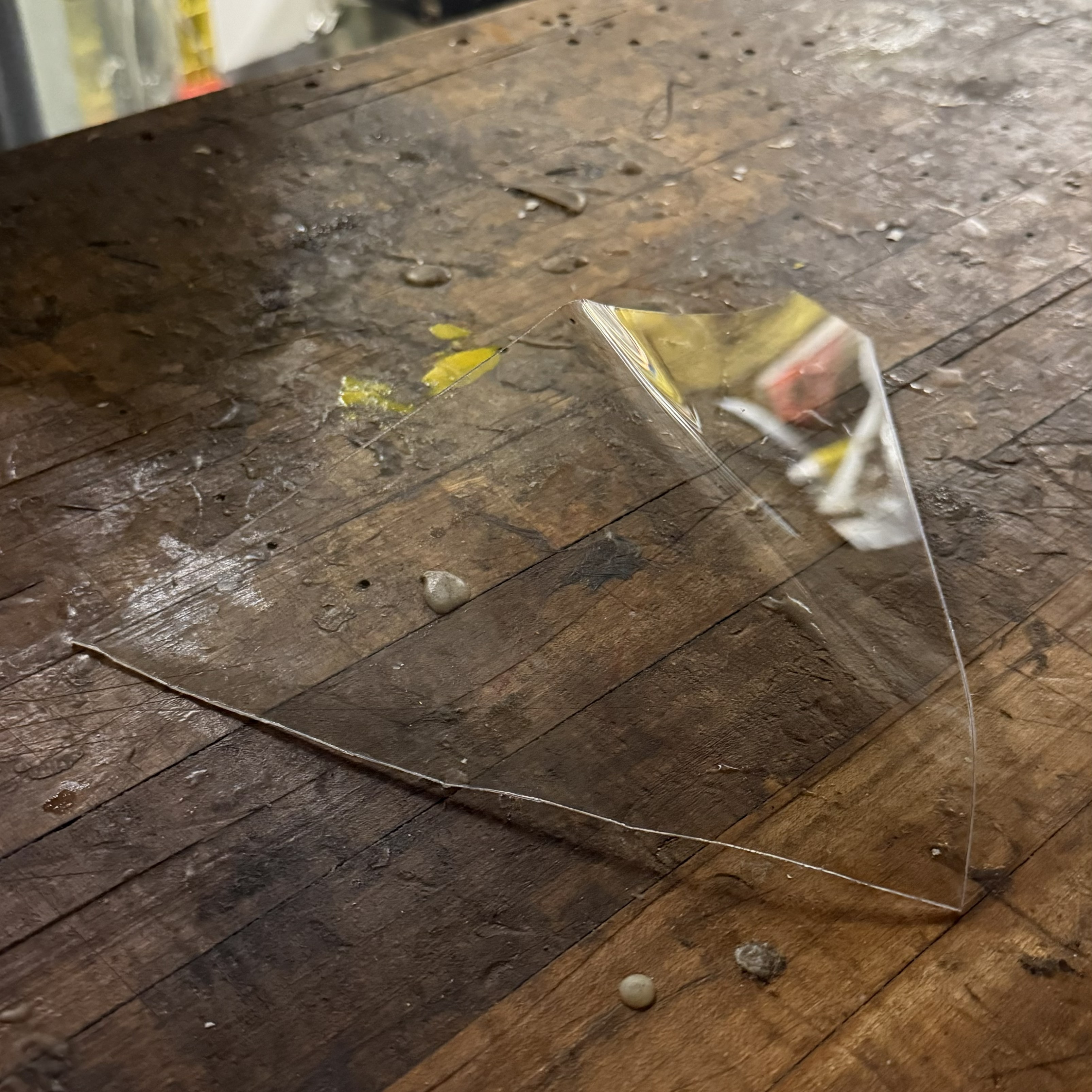
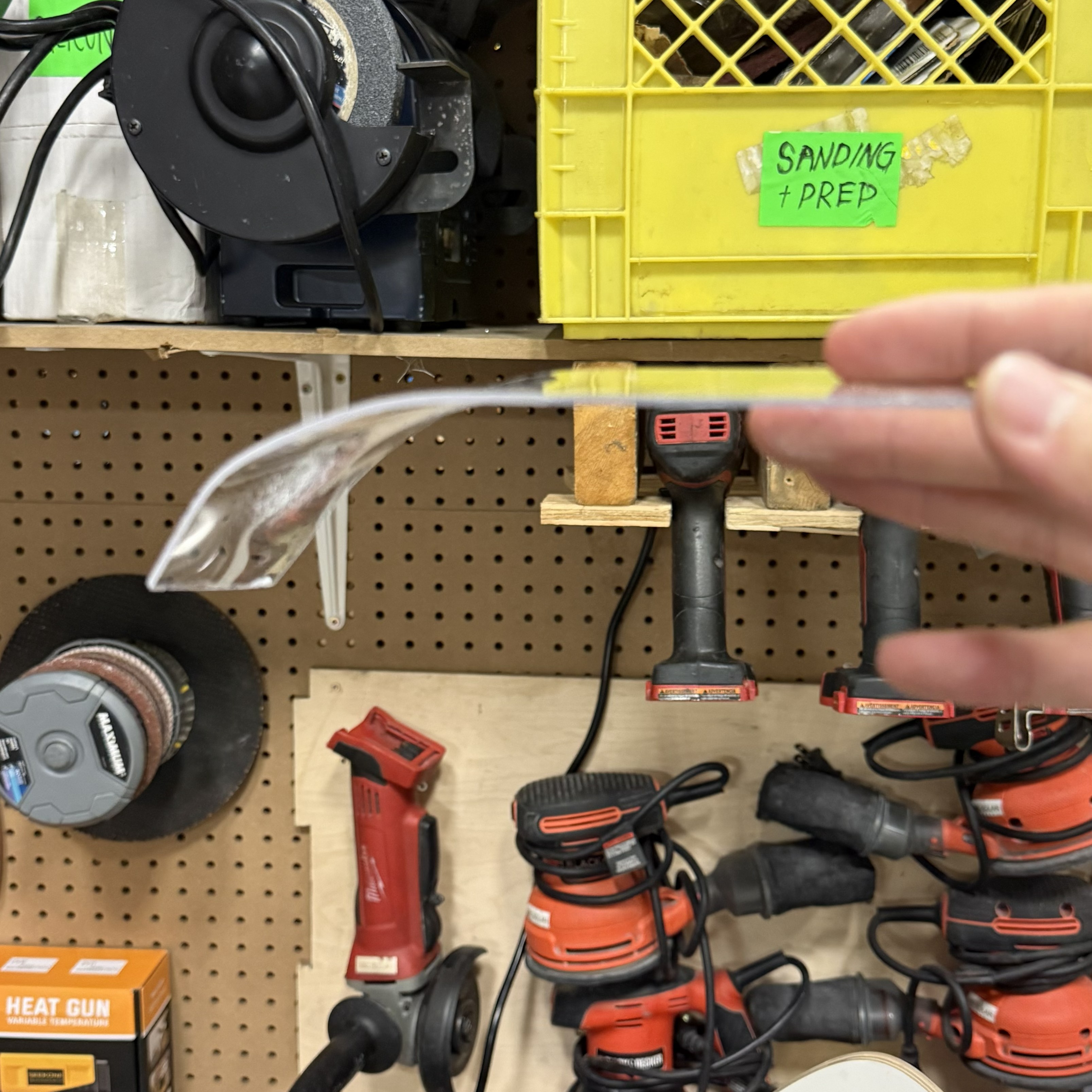
The glass transition temperature of polycarbonate is 140-150 degrees Celsius. We needed to be careful not to exceed 180 degrees Celsius as that is the temperature at which the polycarbonate will start to degrade and melt (which we did not avoid as shown later). There were definitely concerns about whether the heat gun would get hot enough and whether or not the polycarbonate would form as nicely as we had hoped. We were also quite concerned about heat distribution. The heat gun is a very concentrated heat source and we need all parts of the polycarbonte to heat up in order to have a good product.

Brightside Practice Plug side view Brightside Practice Plug bottom view

Test 1 Results

Back Frame isometric view Back Frame top-down view Back Frame front view Back Frame side view

As you can see in the grid of images on the left, the results are pretty bad. In the photo in the top left, is a hand mark of a member pressing down on the polycarbonate sheet trying to form it. This was because we realized that the polycarbonate would not fall onto the aluminum on its own (to be discussed in the method testing section).

The second issue we encountered was distortion. This is shown in the bottom left photo. This is a particular issue because there are visibility regulations that we must meet in order to compete.

Finally, the two photos on the right is showing the degrading and bubbling that we encountered. This was caused by holding the heat gun too close and too long at a specific point on the polycarbonate. We were measuring the temperature of the polycarbonate by pointing a thermal gun at the jig, however, this was horrible as the gun was laggy and never gave us a precise reading. This meant that we were essentially heating the windshield up blindly. This led to the degration and bubbling shown. We even melted some of the paint off the wooden panels.

Method Testing

Diffusion side view Diffusion front view Diffusion fan top-down view Diffusion fan close top-down view

So we did some testing on how we were conducting this thermoforming process in an attempt to improve it for the next test. The first image on the far left is us trying to understand how much the polycarbonate would bend under our force. We heated up the gun and then pushed it together. This proved to us that we could definitely get a clean bend with the heat gun.

Next we tested how well gravity would help us form the polycarbonate. We held the polycarbonate horizontally in the air and then heated it from the top and the bottom. This resulted in the second image from the left. The bend was ok, but we ran into massive degration and bubbling. We learned that even at the glass transition temperature, the polycarbonate isn't just going to fall into any shape we wanted.

Finally we tested this aluminum sandwich method (as shown in photo 3). We took two pieces of alumnium and clamped them with a piece of polycarbonate between them. We then used a large clamp to clamp it in a u-shape. We then heated the aluminum in both the front and back sides. This resulted in the fourth photo. A fairly clean and good polycarbonate bend; where minimal degration and distortion occured.

Thermoforming Test (Jig 2)

The image on the right is the modified test jig. It has been modified to utilize the aluminum sandwich method which showed promise in our previous testing. Some features of the jig that have changed are:

1. Waterjet cut another piece of aluminum to sandwich the polycarbonate. Clmaped them together by using vice grips. The wooden screws are also there to hold the bend of the aluminum.

2. Stripped the paint off the wooden panels so that they won't peel during the test.

3. Moved the placement of the two by four supports and removed the middle one to allow for heating the back of the aluminum.

Built Rig Prototype
Brightside Practice Plug side view Brightside Practice Plug bottom view

Test 2 Results

Back Frame isometric view Back Frame top-down view Back Frame front view Back Frame side view

As you can see the results are great. While its hard to tell in the photos, there is some slight distortion at the front of the windshield but nothing that won't pass the visibility regulations. There is a very consistent and clean bend around the entire windshield. No degration or bubbling occured. Overall an amazing result.

However, the result does not tell the whole story. It was a struggle to heat this thing up. This once again came down to our temperature monitoring system. That thermal gun is just way to unreliable. We never got a consistent or accurate reading. The only reason we took the windshield out of the jig was because we had run out of time for the test. We were under the impression that the polycarbonate hadn't even hit the glass transition temperature because the readings we were getting were so low. We tried manually using probes to measure the aluminum sheets as well but this was not any better than the thermal gun.

Conclusion

While test two was very successful, there are still improvements to the jig that need to be made. For one, a better way to determine the internal temperature of the polycarbonate. We were measuring the metal but that was lower than what the actual polycarbonate temperature was. Next, I'd like to make the bend tighter. This is because I designed the original jig to work with the curavture of our old canopy. As the new canopy has been designed with a much tighter curvature, the jig needs to be adjusted to test for this. Finally, a larger scale test must be done to test whether our method of heating the polycarbonate works at full scale.

The final part of this project is to design an attachment method for the windshield to attach to the canopy of the car. However, due to some restructuring in the aeroshell sub-team, we moved this project to another member. Despite my project being cut-short, I learned a lot about the process of thermoforming and the challenges that come with finding a sponsor.