Benjamin Sheng

The Sailing Effect

Skills: StarCCM+, CFD Analysis

July 2026 - August 2026

Solar cars are built to minimize drag, but a crosswind hits the car's flank at an angle — much like wind filling a sail. This project investigates whether that "sailing effect" can be harnessed for useful thrust instead of just fought as drag. Here are some targets for this project:

1. Quantify the thrust generated by crosswind interaction with the car body

2. Compare one-sail and two-sail configurations

3. Validate results with high-fidelity StarCCM+ simulations

The Sailing Effect

Sailing Effect Report

PDF

This page goes over a fairly basic overview of the sailing effect analysis and the results that came from it. However, for a deeper breakdown of the methodology, simulation setup, and full results, refer to my report titled:

"The Sailing Effect in Solar Car Racing"

The report covers the 3D crosswind simulations I ran in StarCCM+ with 25 prism layers and over 14 million cells, comparing one-sail and two-sail configurations of UBC Solar's car. Please enjoy and feel free to download it.

Overview

Using StarCCM+, I ran 3D crosswind simulations with 25 prism layers and over 14 million cells to study how UBC Solar's car interacts with wind hitting it from the side — effectively acting like a sail.

I tested both a one-sail and two-sail configuration to compare the aerodynamic benefits of each, running more than 15 simulations in total.

The best configuration achieved over 100 newtons of thrust, showing that crosswinds can meaningfully contribute to — or work against — the car's performance depending on the setup.

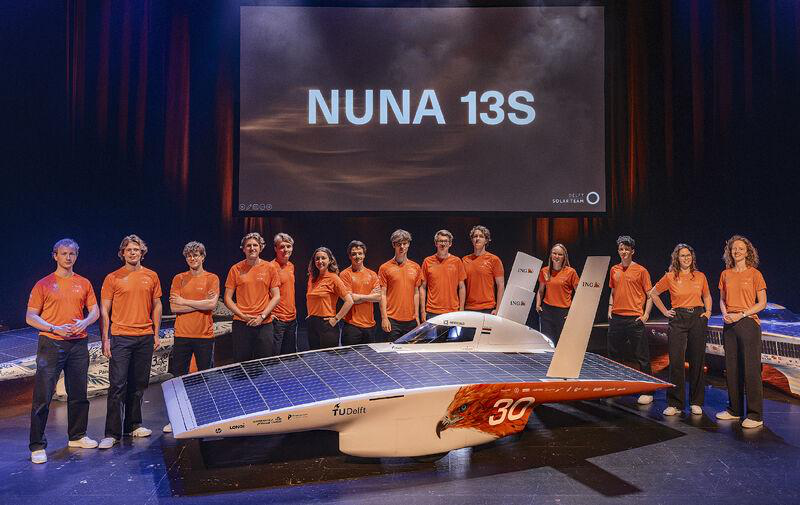
Nuna 13S retractable sail reveal

CAD Methodology

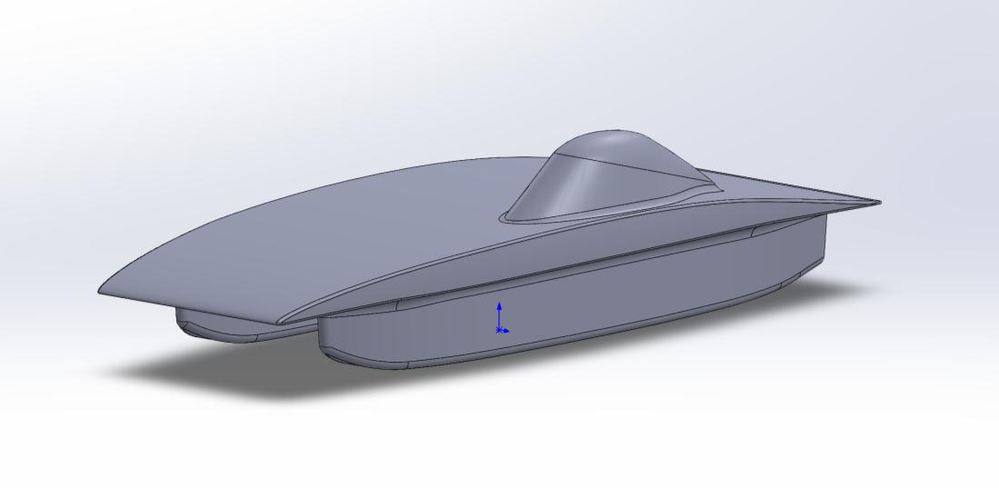
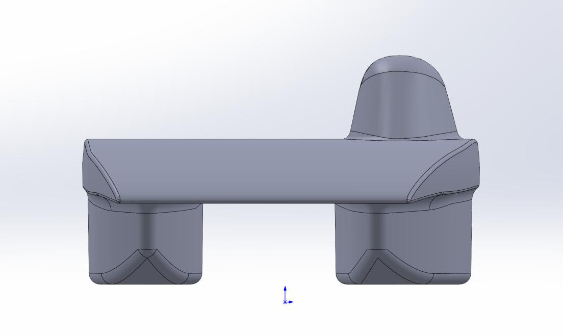
The base of this project is UBC Solar's EP9 catamaran model — a 1.88m by 4.88m twin-hull aeroshell with the driver's canopy on the starboard hull and the battery pack on the portside hull. To isolate the sailing effect, I added vertical airfoils directly onto the existing model with no mechanisms or sub-system integration.

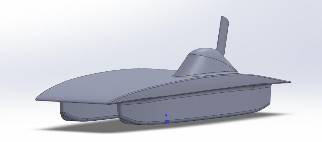
Taking inspiration from the Nuna 13S's retractable sail, I matched its shape in JavaFoil to generate airfoil coordinates, then lofted two sketches at different planes in SolidWorks to build the sail as a solid body. The top was cut to match the canopy's tail contour so it could sit flush against it, resulting in a 20-inch-tall canopy sail.

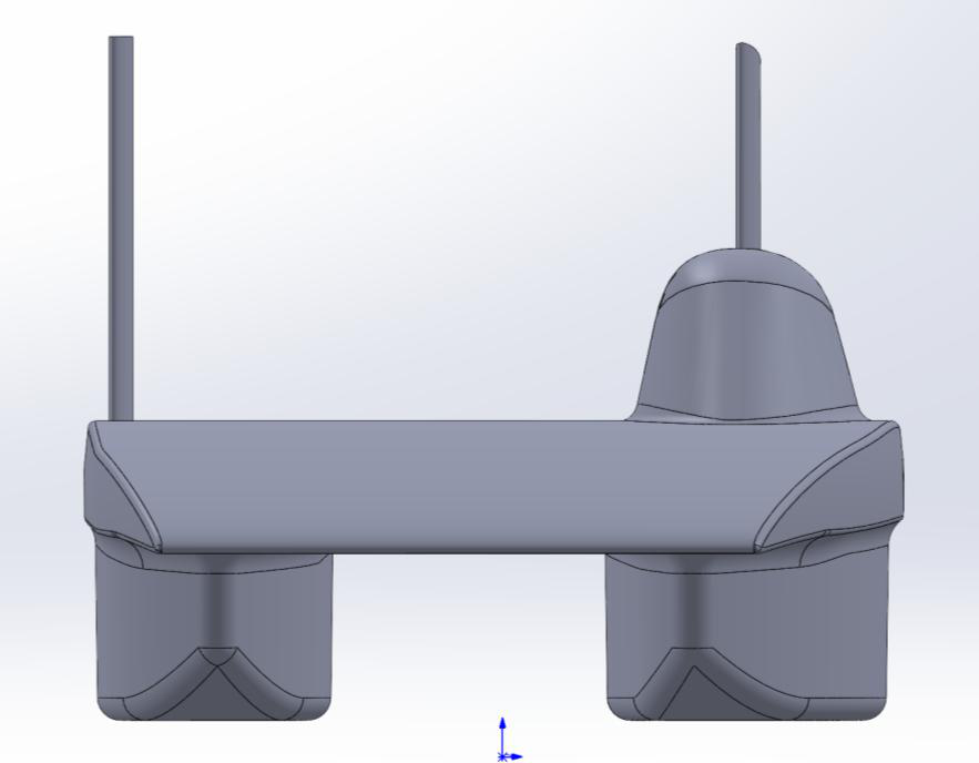
I also modeled a second, 40-inch sail on the port side of the car — mirroring Nuna 13S's dual-sail layout — to test a two-sail configuration in CFD.

Isometric view of the EP9 base model
Front view of the EP9 base model
EP9 with the canopy sail added
EP9 with the 20-inch canopy sail added
EP9 with both sails added
EP9 with both the canopy and port-side sail

CFD Methodology

All simulations ran in Simcenter StarCCM+, split into 2D airfoil sweeps and full 3D car simulations.

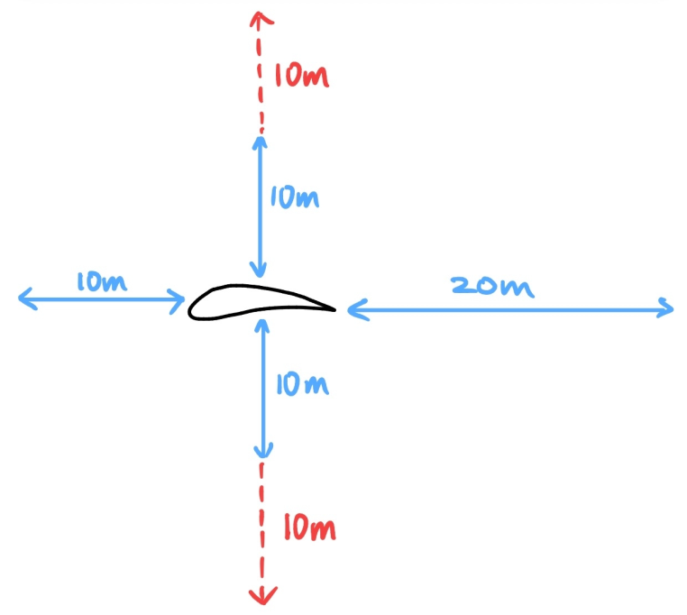
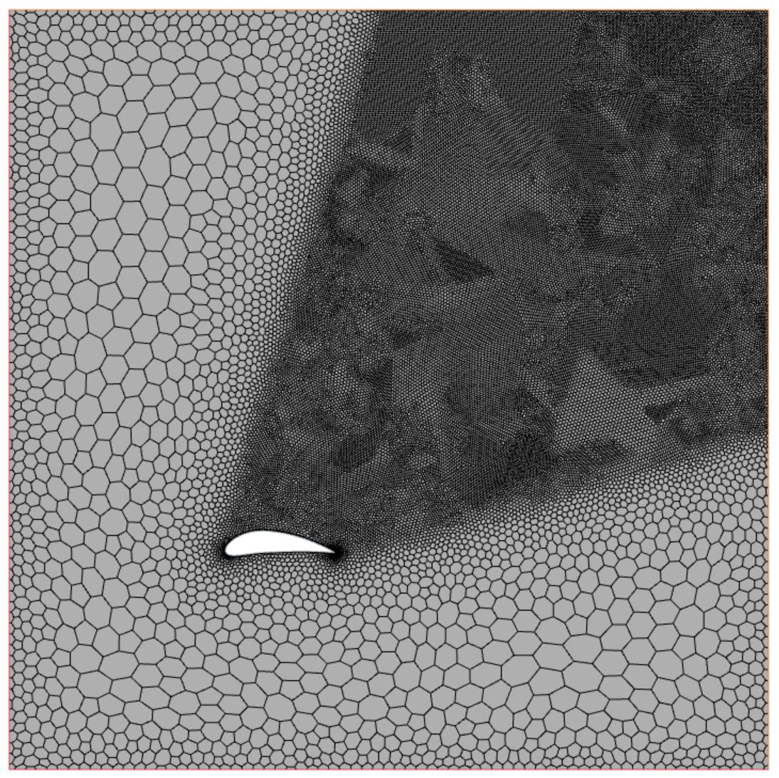
For the 2D cases, each airfoil was extruded 0.1m into a domain 20m behind, 10m in front, and 10m to each side (extended to 20m on the windward side for crosswind cases). A polygonal mesh with a 0.1m base size, 30 prism layers, and 45°-angled wake refinement produced a 45,882-cell mesh — light enough to run 1,000+ iterations across multiple angles of attack (10°, 20°, 30°) with a K-Omega turbulence model.

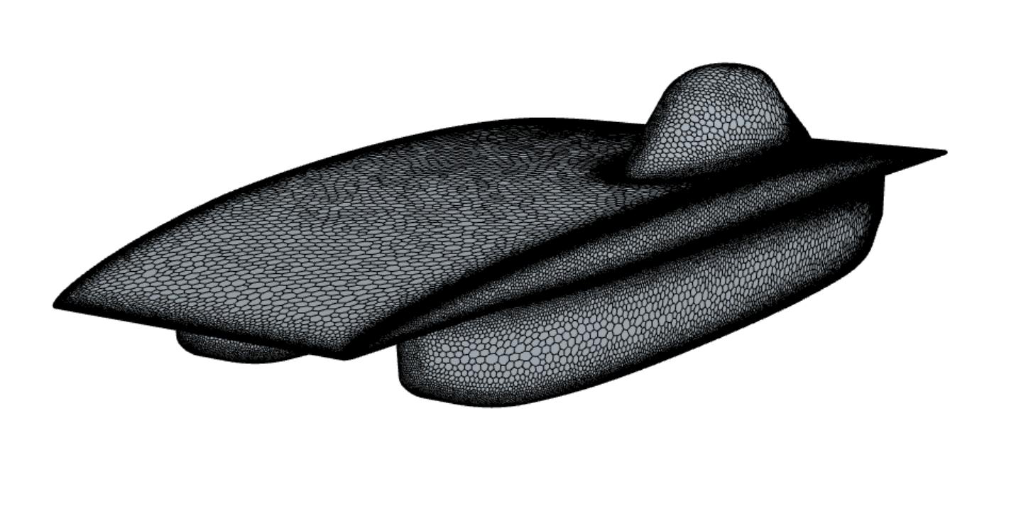
For the 3D car simulations, the domain extended 12m windward, 25m leeward, and 5m tall, with a nested 12m × 12m volumetric control block refining the wake. A polyhedral mesh with 25 prism layers produced roughly 14 million cells. A segregated solver diverged under the combined 80kph forward speed and 60kph crosswind, so I switched to a coupled solver to keep the simulation stable.

These results haven't been validated against real-world data, and hardware limits capped the mesh resolution — a finer mesh would take days to solve, so there's a real accuracy-vs-practicality tradeoff behind every number in this report.
Domain sizing for the 2D airfoil simulations
2D mesh on the NACA10320 airfoil
2D mesh on the NACA10320 airfoil (45,882 cells)
3D surface mesh on the EP9 car body
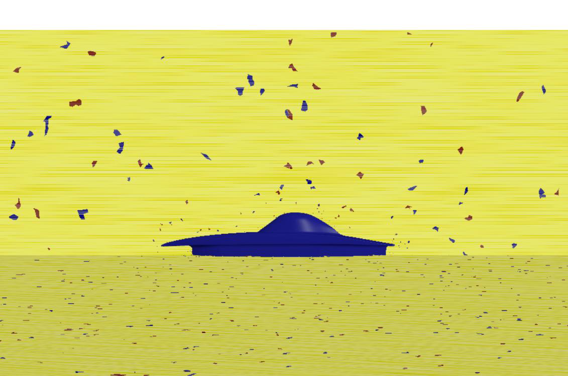
Initialized 3D crosswind simulation

Sail Analysis

I ran five simulations in total: 2D sweeps on NACA10320 and Clark Y airfoils, then 3D runs on the bare EP9 control case, a single canopy-side sail, and a two-sail configuration.

The 2D sweep favored the NACA10320 — it kept generating lift steadily through 30° (78.51 N vs. the Clark Y's 66.73 N), while the Clark Y appeared to stall between 20° and 30°, where its lift plateaued and drag suddenly collapsed.

The bare EP9 control case produced 68.54 N of drag under a 60kph crosswind, dominated by skin friction rather than pressure. Adding a single canopy sail generated 155.24 N of lift, which converts to 35.27 N of thrust at a resolved 12.8° angle — bringing the car's net system drag down to just 2.3 N.

With two sails installed, the battery-side sail (305.02 N lift → 69.30 N thrust) and canopy-side sail (157.2 N lift → 35.71 N thrust) combined for a net 97.56 N of forward thrust — meaning the sails generated more forward force than the total drag of the car and sails combined.

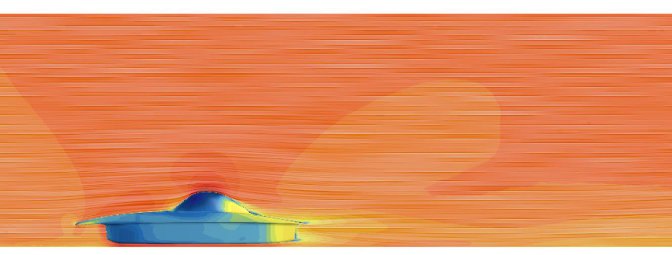
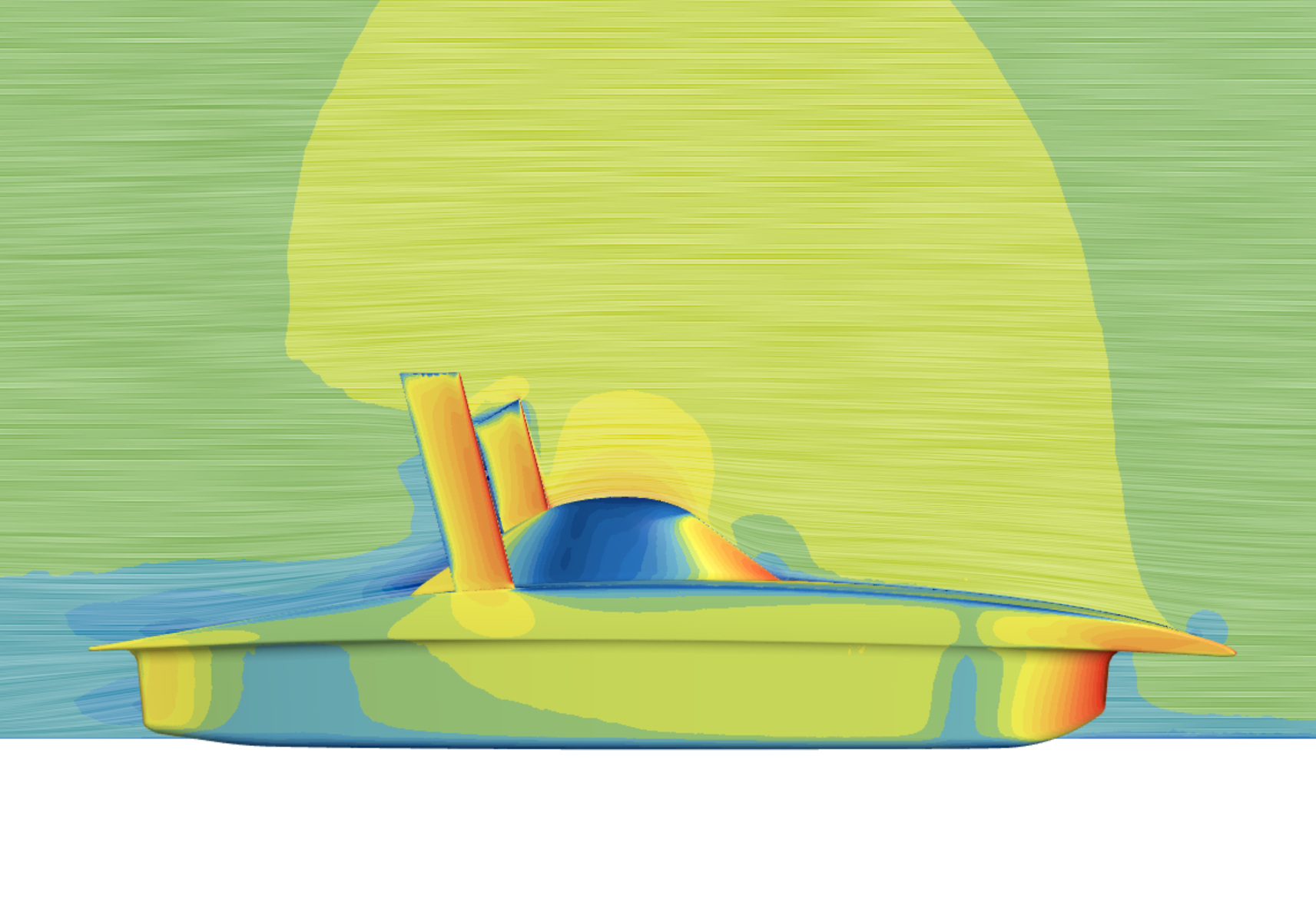
Velocity vector field around the bare EP9 control case
Velocity vector field — control case
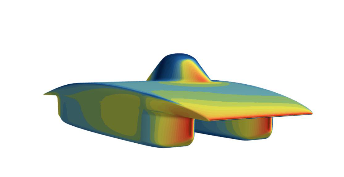
EP9 pressure gradient, control case
Pressure gradient — control case
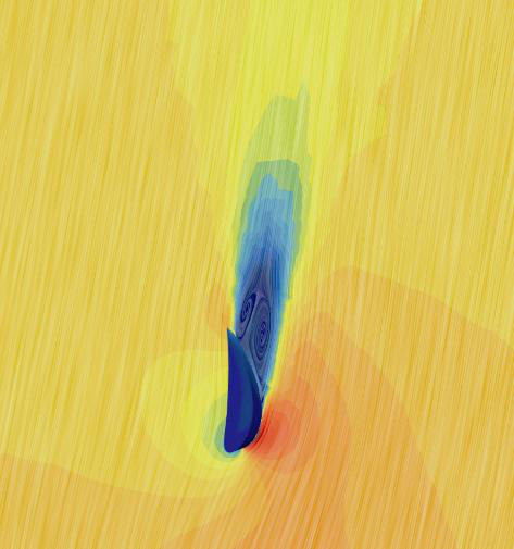
Velocity vector field around the canopy sail
Velocity vector field — canopy sail
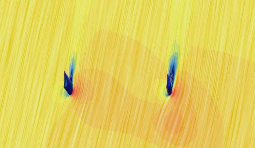
Velocity vector field with both sails installed
Velocity vector field — two sails
Configuration Car Drag (N) Sail Thrust (N) Net Result
Control (no sail) 68.54 68.54 N drag
Canopy sail 54.82 35.27 2.3 N drag
Two sails 58.59 105.01 97.56 N thrust